ABOUT SILICON CARBIDE VARISTORS
Our Silicon carbide varistors are made from about 90% silicon carbide of different grain sizes and 10% ceramic binder and additives. The raw material is formed into various SiC variable resistor geometric dimensions and then sintered under specific atmospheric and ambient conditions at a high temperature creating the repeatable nonlinear resistor characteristics.
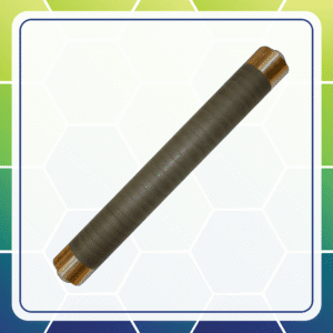
A layer of brass is then flame sprayed onto the SiC varistor as an electrical contact. Other standard metalized contacts include Aluminum, Copper, Nickel, and Silver. In the case of disks, an electrical connection is created by clamping a metal plate to each side of the non linear resistor disk using a tie rod. Large assemblies in the case of disks are fashioned using metal plates with tab connections on each side of these nonlinear resistor disks to create series and parallel stacks of SiC variable resistors to provide appropriate
overvoltage protection for high power. Smaller variable resistor disks simply have tinned copper wires soldered to the brass layer and can be further processed to include a dielectric coating.
Silicon Carbide varistor geometries are manufactured to suit the electric values required by varying the OD, ID, thickness, and length. Our manufacturing process yields good voltage dependences and high energy absorption.
Key features of Silicon Carbide Varistors
- Self-Healing.
- Used in Air/ Oil/ SF6 Environments.
- Configurable into Single or Modular Assemblies.
- Extremely High Ampacity.
- High Surge Energy Rating.
- 100% Active Material.
- Repeatable Nonlinear Resistor Characteristic.
- High Voltage Withstand.
- Essentially Non-Inductive.
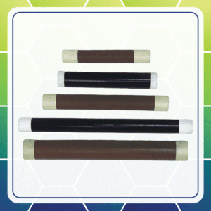
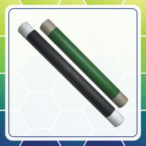
ROD AND TUBE SILICON CARBIDE VARISTORS
These non linear resistors (varistors) are made from SiC and have high power dissipation and high energy absorption. This series of nonlinear resistors are manufactured in rods and tubes with outside diameters ranging from 6 to 30mm and lengths up to 600mm.
The non linear Resistors may be connected in series or parallel for various fields of application. Brass is the standard metallization, but these are also available in aluminum, copper, and zinc. They can operate up to 150C continuously and have essentially zero inductance.
Mechanical Parameters - Rod and Tube Silicon Carbide Varistors
| Description |
Abbreviation |
Range |
| Outside Diameter |
Do |
6 to 30 mm |
| Inside Diameter |
Di |
0 to 8 mm |
| Length |
L |
50 to 600 mm |
| Density |
N/A |
1.9 g / cm³ to 2.0 g / cm³ |
Electrical Parameters - Rod and Tube Silicon Carbide Varistors
| Item |
Range |
| Operating Temperature Range |
-40 to 150°C |
| Ohmic Range |
500 to 17 x 106 Ω/cm |
| Maximum Pulse Residual Voltage |
4.3 x 1.2√(log(R x A x l)) kV/cm |
| Specific Heat Capacity Approximately |
2 J/cm³/°C |
| Inductance |
nH’s (non-inductive) |
Rod and Tube Silicon Carbide Varistors Technical Specifications
| Outside Diameter (mm) |
Inside Diameter (mm) |
Maximum Length (mm) |
Material Type |
Maximum Volume (cm3) |
Maximum Watts @ 20°C |
Maximum Joules @ 20°C (1) |
Tau (s) |
| 6.7 |
0 |
200 |
6770 |
42.1 |
38.6 |
1290 |
45 |
| 25 |
0 |
600 |
64 |
471.2 |
301.3 |
66714 |
221 |
| 30 |
0 |
600 |
64 |
565.5 |
361.5 |
96068 |
266 |
Rod - Silicon Carbide Varistors Material Specification – Outside Diameter 30mm x Length 300mm
| Maximum Length (mm) |
Maximum Volume (cm3) |
Material Type |
Maximum Watts@ 20°C |
Maximum Joules @ 20°C |
Tau (s) |
Heat Capacity (J/ (kg x K) |
Thermal conductivity (W/ cm² x K) |
Temperature coefficient (1/K) |
| 300 |
2120.6 |
6770 |
259.3 |
51718 |
199 |
856 |
0.00611 |
-2.85E-04 |
| 300 |
2120.6 |
64 |
180.8 |
48034 |
266 |
917 |
0.00492 |
-1.84E-04 |
| 300 |
2120.6 |
82 |
226.7 |
323 |
1.4 |
6 |
0.00617 |
-1.05E-10 |
SiC Varistor Rod and Tube Applications
- Generator protection - protect synchronous power generator damage during a shutdown. Rods or tubes absorb high energy in the field winding of a generator exciter. These are used both permanently and switched in protection to discharge the energy stored in the field coil of the generator acting as an excitation field limiter.
- Magnet coil field discharge of large industrial electromagnetic lifting magnets.
- Mitigate transient damage produced during the de-excitation of a synchronous motor by reducing the field current fast as possible, minimizing short-circuit current as part of an excitation field limiter.
- Switch contacts with inductive load.
- High switch-off voltages in transformers.
- Mains overvoltage from lightning, inductive or capacitive coupling.


