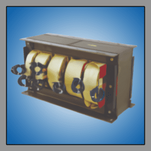
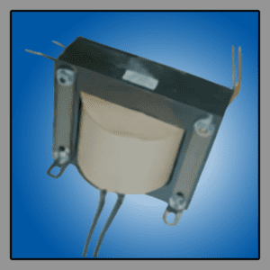
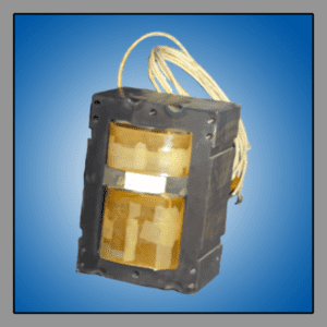
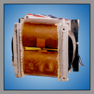
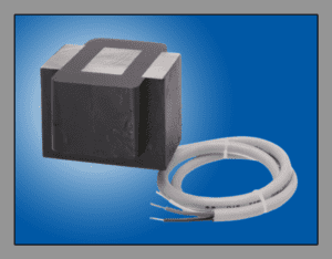
ABOUT LINE FREQUENCY TRANSFORMERS
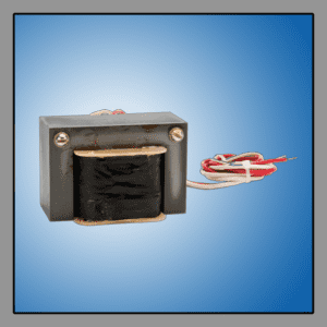
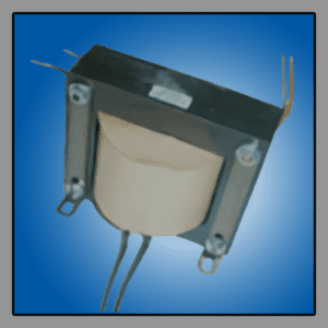
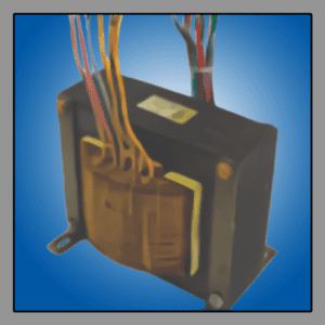
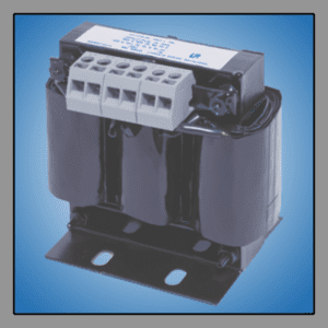
A transformer converts alternating current (AC) from one voltage to another and works by magnetic induction. Transformers consist of a magnetic core and two or more coils of insulated wire which are wound around the magnetic core. The magnetic core contains the magnetic flux created by alternating current flowing through the primary winding. The magnetic flux in the core is then coupled to a secondary winding such that when voltage is introduced in the primary coil, it magnetizes the core, inducing a voltage in the secondary or output coil.
The difference in the number of turns in the primary and secondary create a step-up or step-down in voltage. Taps can be provided on the high voltage winding to correct for high or low voltage conditions, and still deliver full rated output voltages at the secondary terminals. We use magnetic cores with low losses grain-oriented silicon steel for the best performing transformer. Insulative material is used to create isolation from winding to winding and winding to core.
To attenuate transient noise and avoid the transfer of over-voltage/pulse voltage passing by the capacitive coupling of the windings, an electrostatic screen may be used. This is placed between the primary and secondary windings.
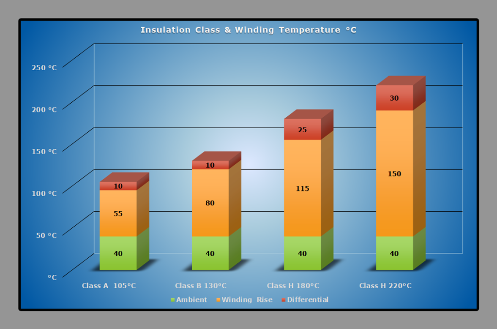
Our transformers and inductors are designed to thermal class A, B, F or H depending on application or standards needed.
| Insulation / Thermal Class | Max temperature (°C) | Reference max ambient temperature (°C) | Max temperature rise (°C) |
|---|---|---|---|
| A | 100 | 40 | 75 |
| E | 115 | 90 | |
| B | 120 | 95 | |
| F | 140 | 115 | |
| H | 165 | 140 | |
| C | >165 | >140 |
Insulation class takes into account the temperature rise of the windings and insulation above the existing ambient temperature. These classes describe the insulating materials operating temperature ratings. Letter classifications are used for different designations of system temperatures in degrees Celsius. The system temperature is the maximum temperature at the hottest spot in the winding. Standard features of our magnetics include insulation voltages up to 6kV, 50/60Hz operation, double insulated materials, and class F (155°C) or class H (180°C) insulation.
 For cost sensitive applications aluminum windings are also an available option.
For high power transformers typically above 30kVA, cooling channels may be utilized to create airflow between the windings in order to enhance the heat transfer from the transformer winding to the ambient air.
Design parameters needed for a transformer:
- Primary voltage and frequency.
- Secondary voltage required.
- Capacity required in volt-amperes.
AUTO TRANSFORMERS
Auto transformers are used strictly in a step-up or step-down application. They are very similar to isolation transformers with one important exception. In an auto transformer the primary and secondary windings are electrically common to each other.
The advantage of using an auto transformer over an isolation transformer is its smaller size, it’s lighter and costs less. The major disadvantage is that there is no isolation between the primary and secondary windings, which allows noise on the power line to be directly coupled to the load.
Another disadvantage is that auto transformers provide no regulation. It is also important to note that the greater the change in voltage the less cost effective the auto transformer is. Some common applications for auto transformers are motors, heaters, and other non-sensitive loads.
SINGLE-PHASE AUTO TRANSFORMERS
With power ratings up to 25kVA Primary voltages up to 1000 V IP (Ingress Protection): IP20 Applicable Standards: CEI 96-3 CEI 96-13 EN 61558-1 EN 61558-2-13THREE-PHASE AUTO TRANSFORMERS
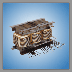
With power ratings up to 150kVA Primary voltages up to 1000V IP (Ingress Protection): IP20 Applicable Standards: CEI 96-3 CEI 96-13 EN 61558-1 EN 61558-2-13POWER TRANSFORMERS
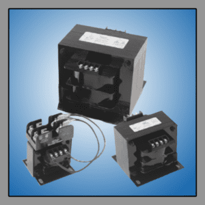
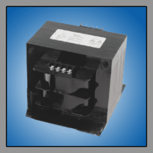
Power transformers include insulating or isolating transformers. These terms are used to describe the "electrical isolation" of the primary and secondary windings, or insulation between the two. Often an electro-static copper shield is placed between the windings to reduce electrical noise from primary to secondary. A grounded electro-static shield provides a safety factor preventing accidental contact between windings under faulty conditions.
These can also be referred to as step-up or step-down transformers because they are used to either increase or decrease incoming voltage. They are designed to do both (i.e., 120/208/240V in and 120/240V out) to handle worldwide voltages. Another very common application would be to step down voltage for DC rectification. Most voltages can be accommodated where most voltages are typically under 6kV for small units and 10kV for large units. Sizes are available in single-phase or three-phase up to 250kVA.
Control Power transformers are primarily used in a step down environment to power low voltage circuits and / or accessories. Note that a single-phase transformer can be used on a three-phase source by connecting the primary leads to any two wires of a three-phase system. This is irrespective of whether the source is three-phase 3-wire or three-phases.
Single-Phase Power Transformers
UL Approved With power ratings from 50 to 50kVA Primary voltage inputs up to 1000V Secondary voltages up to 1000V IP (Ingress Protection): IP20 Applicable Standards: CEI 96-2 CEI 96-8 CEI 96-9 EN 61558-2 EN 61558-4 EN 61558-6 EN 61558-2-1 EN 61558-2-4Three-Phase Power Transformers
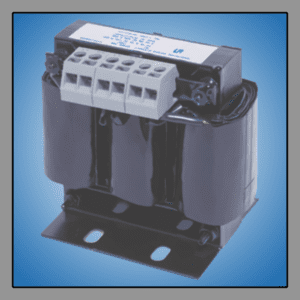
UL Approved With power ratings from 1000 to 100kVA Primary voltage inputs up to 1000V Secondary voltages up to 1000V IP (Ingress Protection): IP20 Applicable Standards: CEI 96-3 CEI 96-8 EN 61558-1 EN 61558-2-1 EN 61558-2-4RAILWAY MAGNETICS
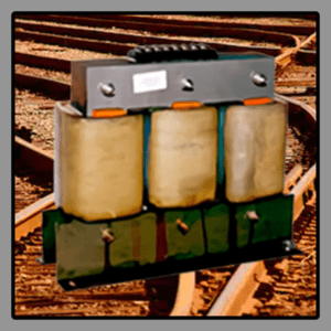
The proper functioning of the railway signaling depends on top quality components to ensure the safe transport of people and goods. For rail transport applications we make special magnetics to support railway signaling lights or electro- mechanical devices for switching or rail heating. We provide the following types of magnetics for these applications:
- Transformer: three-phase, single-phase.
- Impregnated Transformers.
- High voltage transformers.
- 1000V rated transformers.
- Coil Interphase.
- Single-phase transformer low inductance.
- Low-voltage transformers.
- Transformer Box.
- Six-phase transformers.
- Transformers with internal inductance.
These transformers for railway signaling feature:
- Cooling: AN
- Insulation class: II
- Thermal class materials: H
- Applicable Standards:
- CEI 14-8
- CEI EN IEC 60076-11
- EN 61558-1
- IS 365 and 2008
- IP (Ingress Protection): IP40
SATURABLE REACTORS
These are used to vary the output current of a reactor using a separate winding to introduce a DC current to the reactor. This is done to change the saturation level of the reactor. A specific application is to infinitely vary the current to an arc lamp.
This is done to smoothly adjust the lamp output power, i.e., “Dial-A-Watt.” In this case the reactor is connected across the capacitors in a ferroresonant ballast to control the lamp power. Changes in primary voltage "swings" have no effect, such that the lamp output remains constant regardless of changes in input voltage, as long as the input range changes no more than +/-20%.
AUDIO TRANSFORMERS
These operate at frequencies between about 20Hz to 20kHz. Typical uses are for audio amplifier circuits in older tube-based designs to match the high impedance outputs of these amplifiers to low impedance loudspeakers.
FERRORESONANT - CONSTANT VOLTAGE TRANSFORMERS
We provide four types of Ferroresonant Transformers:
- Square-Wave in Sine-Wave out
- DC output
- Sine-Wave in Sine-Wave out
- Controlled Ferroresonant
Square-Wave in Sine-Wave out
This ferro has a shaping winding which takes a square-wave or a low voltage "pulsed square wave" generated by an inverter and battery, and converts it to an AC sine-wave where voltage is regulated 1% to 5% depending on your requirement. The typical size range for this product would be 100VA through 25kVA, 50Hz or 60Hz. However, we can produce inverter transformers with any VA rating and input. These are primarily used in uninterruptible power supplies.DC Output
This ferro is used primarily in brute force DC power supplies. The ferroresonant transformer takes a sine wave input and creates a regulated square wave output, which is ideally suited for rectification. The square wave will produce a lower ripple than a sign wave using the same filter capacitor. Sizes are 25W to 10kW, 50Hz, 60Hz, or 50/60Hz.Sine-Wave in Sine-Wave out
This ferro takes a sine-wave input and produces a sine wave output with a choice of output voltage variations of 1%, 3%, or 5% for an input voltage variation of 10% to 20%. These are used in integrated power protection systems, protecting the critical load from all power problems with the exception of a blackout. Multiple voltages are available so this transformer can replace a multi-tap input transformer. This product is available in sizes from 30VA through 75kVA single-phase or three-phase, 50Hz or 60Hz.Controlled Ferroresonant
This is a special type of ferroresonant transformer that has an additional winding in which a variable DC control voltage is applied. When this winding is used in conjunction with a feedback circuit, the transformer provides much tighter secondary regulation. This can also be used to add flexibility to the output voltage based on the designer’s requirements, for example, regulation adjustment for different frequencies.FOIL WOUND TRANSFORMERS
Foil wound transformers are used in high current applications. The coil is wound with either copper foil or aluminum foil. These transformers are used when low voltage and high current is required.
Additional benefits include improved temperature dissipation, reduction of hot spots, improved vibration capabilities, and reduced layer-to-layer voltage stress, yielding improved dielectric strength required for rugged applications. The reduced weight of the company’s foil wound transformers ensures that it is the ideal solution for restricted weight and volume challenges.
EDGE WOUND TRANSFORMERS AND COILS
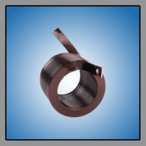
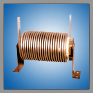
Edge winding is a technique in which a rectangular magnet wire is wound on its narrow edge. This allows a much greater surface area to dissipate more heat than conventional winding techniques, and produces coils that reduce skin effect and proximity losses compared to traditional winding methods.
Edge winding also produces coils with few undesirable parasitic elements making it more appropriate for use in inverters and converters, using high frequency silicon carbide (SiC) and gallium nitride (GaN) semiconductors. It also produces lower parasitic capacitance reducing unwanted high frequency noise, which is a concern when passing electromagnetic compatibility (EMC) testing. Edge winding is used mainly in isolation transformers and inductors that have high load currents at lower voltages. Chokes and transformers can be up to 10% lighter and reductions in power losses of up to 25% are achievable when compared to existing winding methods.
A single-layered edge-wound coil when combined with liquid-cooling produces a durable leakage transformer for use in railway or electric vehicle (EV) applications.
VIBRATORY FEEDER COILS
The vibratory inductor is a unique application for a simple choke design, for use in Vibratory Feeding Systems and Sorting Lines or Bowls. Vibrations are set up between an I-armature assembly and an E-armature assembly through the changing magnetic field of the core.
The E-armature is usually secured to the solid equipment base, while the I-armature is secured to the bowl or line to be vibrated. The two armatures are positioned only a fraction of an inch from each other so that the E’s and I's are coupled through the magnetic field. This gap can be variable to change the strength of vibrations.
Coils can be provided potted or unpotted and are available with heavy weldments for solid attachment to the vibratory unit. Terminations are provided through flying leads, STO line cords, solder lugs, or quick connect lugs.
