- Standard Toroidal Isolation Transformers
- Toroidal Transformer Construction
- Medical Grade Isolation Transformer
- Low Profile PC Mount Toroid Transformers
- Features of Toroidal Transformers
- Low Profile Miniature 50/60Hz Transformers
- Toroidal Power Inductors
- Toroidal Transformer vs Standard Transformer
- Current Transformers
- Standard Toroidal Auto Transformers
- Toroidal Power Inductors
ABOUT TOROIDAL TRANSFORMERS
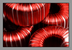
There are several advantages of toroidal transformers. These are power transformers utilizing a toroidal core.
Primary and secondary coils are wound on this core and the toroidal shape allows for a shorter mean length per turn, reducing I2R losses in winding which are the main losses in this type of transformer yielding a smaller design improving overall efficiency.
HOW TO MAKE A TOROIDAL TRANSFORMER
Line frequency toroidal transformers start with a core made from a continuous strip of thin, typically M4, grain-oriented electrical grade silicon steel. Silicon grains in the steel are oriented based on the rolling direction of the steel and are slit parallel to that orientation, creating the preferred path for magnetic flux.
Strips are available in numerous widths; for smaller and mid-sized cores these are typically available in 1mm increments, and larger toroidal cores strips are available in 5mm increments. This steel has a thin inorganic coating for high interlaminar resistance, providing insulation between lamination windings and a good stacking factor. To create the core, a strip of grain-oriented electrical grade silicon steel is tightly wound under controlled conditions and tension on a mandrel, similar to a clock spring with the ends spot-welded in place, assuring a firm and congruous magnetic path.
Unfortunately winding of the core creates mechanical and magnetic stresses, which change the molecular structure of the core. To return the material to a full stress relief condition, the core is placed in an annealing furnace. Using a precise heating and cooling profile ensures that the silicon grains are in the single preferred magnetic direction.
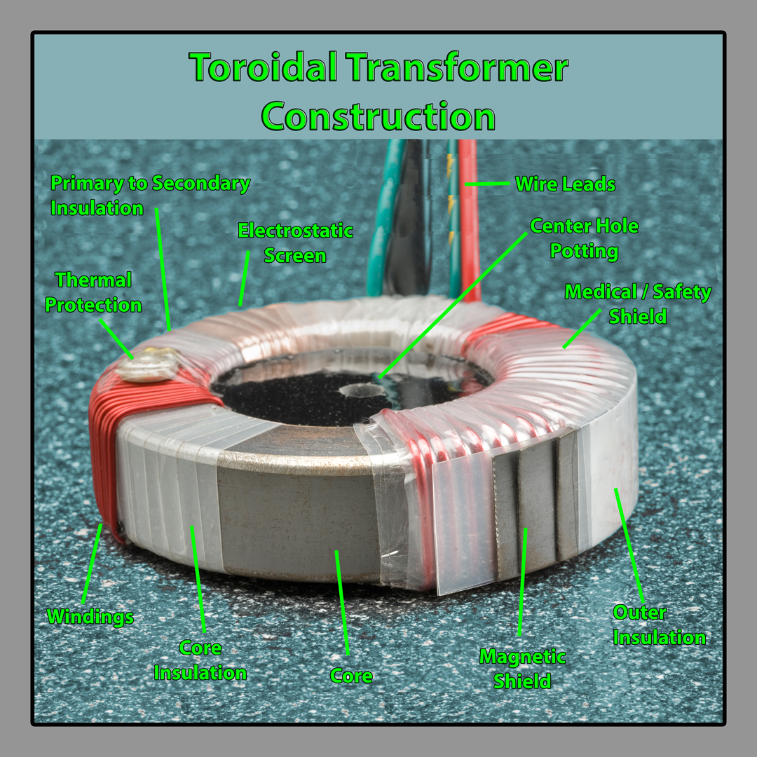
When comparing a toroidal transformer vs standard transformer, a toroidal transformer core insulation consists of four layers of 2mil polyester film (other materials are available) applied to the core using a toroidal tape winding machine. This insulation provides 100% surface coverage, also protecting and cushioning the core from the windings and reducing vibration.
Primary windings are applied by a toroidal winder and if needed lead wires are attached. The primary to secondary insulation uses the same process and materials as the core insulation, to meet the standard test requirement of 4 kV RMS for 1 minute between primary and secondary. Secondary windings are applied by a toroidal winder and if needed lead wires are attached.
The copper wire has a base coat of polyester and a heavy topcoat of an amide imide (200°C). The copper wire is wound uniformly over the entire core to provide: better heat dissipation, minimum flux leakage, and to maintain a low voltage between adjacent turns. The outer insulation is then applied using the same process and materials as the other insulation layers, except only two layers of polyester film are used.
Toroidal Transformer Design Options
Thermal Protection - Usually in the primary circuit, normally closed-auto reset opens at high-temperature UL, CSA, VDE listed components.
Center Hole Potting - Thermoplastic material for high mounting precision. A threaded insert or press-fitted stud is optional. A thermally conductive compound is available.
Electrostatic Screen - Copper foil (2mil) laminated between polyester film and tape to reduce capacitive coupling between primary and secondary windings, tightly wound over primary insulation.
Medical / Safety Shield - Polyester laminated (5mil) copper foil creates a physical barrier between primary and secondary windings, terminated at one end with green and yellow earth wire to meet UL 2601 and IEC 601 (also ideal for audio toroidal transformers and used in toroidal transformer amplifiers).
Magnetic Shield - Several turns of silicon grain-oriented silicon steel are tightly wound around the toroidal circumference, fixed in place by outer insulation. Can also be useful in audio toroidal transformers and toroidal transformer amplifiers.
Toroidal Transformer Mounting Kit Options
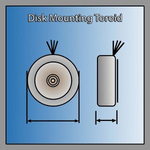
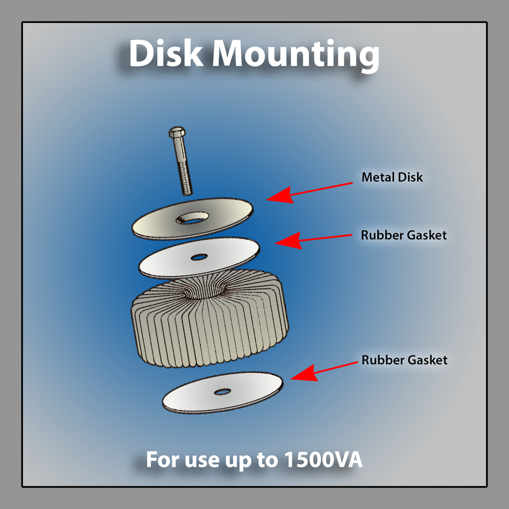
Disk Mounting
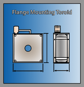
Flange Mounting
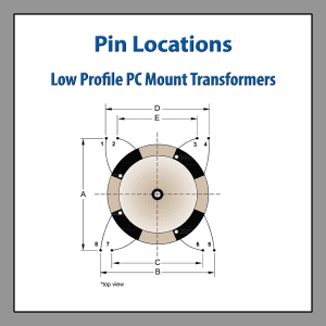
PCB Mounting Pinout
Toroid Metal Disk Mounting Exploded View
Uses of Toroids for your line frequency applications
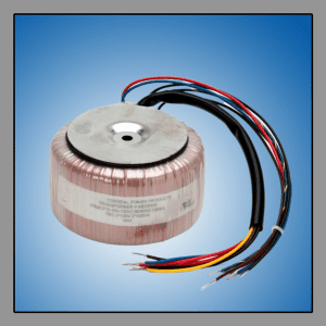
50/60Hz power toroidal transformers have unmatched flexibility and efficiency providing a higher performance compact transformer. Since there is no air gap, it results in a stacking factor of 97.5% of its weight. Power toroidal transformers can also operate at higher flux densities than standard E-I laminated transformers, thus reducing the number of turns necessary to induce a given voltage across the same cross-section of the core.
This means a lower series resistance in the winding, reducing the I2R copper losses. Given the same power output requirements, ambient temperature, and temperature rise allowances, a toroidal transformer vs standard transformer will use less material to produce an equivalent transformer leading to a smaller and lighter solution than an equivalent standard laminated transformer. Uses of Toroids are also well suited for audio toroidal transformer applications and toroidal transformer amplifiers. With all the above reasons the question should not be “Why to choose a toroidal transformer,” it should be why not!
ARE TOROIDAL TRANSFORMERS BETTER?
Simplified Mounting

A one bolt mounting scheme easily and quickly mounts the toroid, avoiding costly mechanical design and tooling charges associated with the first piece of custom conventional E-I laminated transformers.
A power toroid, toroidal autotransformers, and toroidal medical-grade isolation transformers have a low center-of-gravity along with reduced weight, such that a lower gauge sheet metal is required to support a toroidal transformer. There are many uses Of Toroid, namely to further reduce your product’s weight and material and labor cost by eliminating three screws per assembly.
When comparing toroidal transformer vs standard transformer, a toroidal power transformer has extremely low no-load losses.
When used in an application where a circuit is in a quiescent or “stand-by” mode for long periods, the potential power reduction can be significant, sometimes 80% to 90% lower
Low No-Load Losses

Low Weight

Because they are more efficient, toroid isolation transformers and toroidal autotransformers can be up to 50% lighter (depending on power rating) than E-I laminated transformers.
Low weight simplifies end product design by reducing mounting hardware and supporting enclosure requirements.
The core of a toroid transformer is formed from a single strip of grain-oriented electrical grade silicon steel, tightly wound in the form of a clock spring with the ends spot-welded in place.
The copper wire is wound over the polyester film, forming a silent, stable design without the use of environmentally harmful glues or varnishes. It will not clack or buzz anywhere near the level as would many pieces of separate lamination under the same changing magnetic field. The magnetic field of a toroid core intensifies the field, not contributing to the problem of layer-to-layer vibration.
Low Acoustical Noise

Higher Efficiency
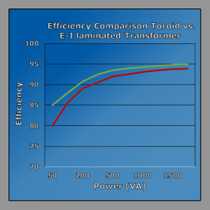
The combination of very low core losses (1/2 watt per pound), a lower mean length per turn, and fewer turns yield lower I2R losses.
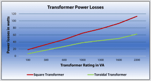
This unique toroidal transformer construction allows toroidal transformer vs standard transformer to be typically between 15% and 30% more efficient. As a rule, the larger the transformer the more efficient a toroidal transformer becomes.
Since most of the losses in a toroid transformer are in the copper wire, the toroid cools off quicker than the conventional E-I transformer type with more iron.
At half the load, the toroidal transformer’s temperature rise is only about 30% of what it is at full load.
Lower Operating Temperature
Radiate Lower Magnetic Fields
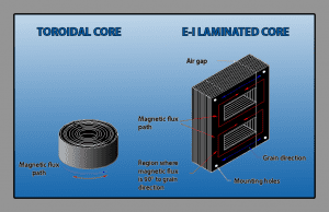
Toroidal transformer vs standard transformer (including toroidal medical isolation transformers) is made from one solid piece of material focusing on the field within the core. In addition, the primaries and secondaries are wound uniformly around the entire core.
This results in very low radiated magnetic fields. The toroidal transformer is perfect for applications with circuitry, which is highly sensitive to stray magnetic fields. In certain cases, the single bolt mounting allows the toroid to be rotated in place, to yield the best possible results without any additional tooling or sheet metal work.
This can be specifically important in medical equipment having especially sensitive electronics; a toroidal medical isolation transformer typically can be placed in closer proximity to these electronics without additional shielding. Can also be useful in audio toroidal transformers.
Toroidal power transformers have a lower core loss, operate at a higher flux density, and allow the conductive windings to be in intimate contact with the core. This enhances current flow at all points in the core yielding a transformer, which is smaller than its E-I transformer counterpart.
Electrical and mechanical designers appreciate a toroid’s compact dimensions, especially where low height is a consideration.
Small Size

Flexible Dimensions

Power toroids and power chokes are not constrained to specific lamination sizes.
Since the height and diameter of toroids may be carefully varied, uses of toroid allow flexibility to accommodate the specific height and width design requirements.
STANDARD TOROIDAL ISOLATION TRANSFORMERS
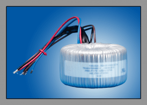
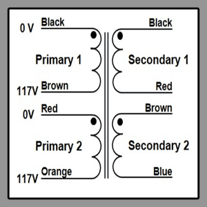
These standard toroidal transformers provide general isolation for general purpose applications for most electrical products which require a step-down or step-up in voltage. They consist of dual 117 V primaries and dual secondaries. Power capacity ranges from 100 to 3,000 VA.
By offering dual primaries these are easily configurated for 120 V or 240 V operation. Dual secondaries range from 2 to 12 V windings to 2 to 120 V windings. This variety offers the option of stepping down/stepping up your line voltage or simply providing isolation from your voltage source to your equipment.
| Part Number | VA Rating | Secondary Voltage | OD | Height | Weight | Secondary Current | Competitor P/N Reference |
|---|---|---|---|---|---|---|---|
| XF-00100-2012 | 100 | 2 x 12 | 3.8" | 1.8" | 2.4 | 2 x 4.16 | AA50952-012 |
| XF-00100-2015 | 100 | 2 x 15 | 3.8" | 1.8" | 2.4 | 2 x 3.33 | AA50952-015 |
| XF-00100-2018 | 100 | 2 x 18 | 3.8" | 1.8" | 2.4 | 2 x 2.77 | AA50952-018 |
| XF-00100-2024 | 100 | 2 x 24 | 3.8" | 1.8" | 2.4 | 2 x 2.08 | AA50952-024 |
| XF-00100-2030 | 100 | 2 x 30 | 3.8" | 1.8" | 2.4 | 2 x 1.66 | AA50952-030 |
| XF-00160-2012 | 160 | 2 x 12 | 4.0" | 2.2" | 3.6 | 2 x 6.66 | AA51852-012 |
| XF-00160-2015 | 160 | 2 x 15 | 4.0" | 2.2" | 3.6 | 2 x 5.33 | AA51852-015 |
| XF-00160-2018 | 160 | 2 x 18 | 4.0" | 2.2" | 3.6 | 2 x 4.44 | AA51852-018 |
| XF-00160-2024 | 160 | 2 x 24 | 4.0" | 2.2" | 3.6 | 2 x 3.33 | AA51852-024 |
| XF-00160-2030 | 160 | 2 x 30 | 4.0" | 2.2" | 3.6 | 2 x 2.66 | AA51852-030 |
| XF-00160-2120 | 160 | 2 x 120 | 4.0" | 2.2" | 3.6 | 2 x 0.66 | AA51852-117 |
| XF-00225-2012 | 225 | 2 x 12 | 4.6" | 2.2" | 5.1 | 2 x 9.27 | N/A |
| XF-00225-2015 | 225 | 2 x 15 | 4.6" | 2.2" | 5.1 | 2 x 7.5 | AA52402-015 |
| XF-00225-2018 | 225 | 2 x 18 | 4.6" | 2.2" | 5.1 | 2 x 6.25 | AA52402-018 |
| XF-00225-2024 | 225 | 2 x 24 | 4.6" | 2.2" | 5.1 | 2 x 4.68 | AA52402-024 |
| XF-00225-2030 | 225 | 2 x 30 | 4.6" | 2.2" | 5.1 | 2 x 3.75 | AA52402-030 |
| XF-00225-2120 | 225 | 2 x 120 | 4.6" | 2.2" | 5.1 | 2 x 0.93 | AA52402-117 |
| XF-00300-2015 | 300 | 2 x 15 | 4.6" | 2.9" | 6.5 | 2 x 10 | AA53002-015 |
| XF-00300-2018 | 300 | 2 x 18 | 4.6" | 2.9" | 6.5 | 2 x 8.33 | AA53002-018 |
| XF-00300-2024 | 300 | 2 x 24 | 4.6" | 2.9" | 6.5 | 2 x 6.25 | AA53002-024 |
| XF-00300-2030 | 300 | 2 x 30 | 4.6" | 2.9" | 6.5 | 2 x 5 | AA53002-030 |
| XF-00300-2042 | 300 | 2 x 42 | 4.6" | 2.9" | 6.5 | 2 x 3.65 | N/A |
| XF-00300-2120 | 300 | 2 x 120 | 4.6" | 2.9" | 6.5 | 2 x 1.25 | AA53002-117 |
| XF-00400-2024 | 400 | 2 x 24 | 5.4" | 2.4" | 7.2 | 2 x 8.33 | AA53752-024 |
| XF-00400-2030 | 400 | 2 x 30 | 5.4" | 2.4" | 7.2 | 2 x 6.66 | AA53752-030 |
| XF-00400-2042 | 400 | 2 x 42 | 5.4" | 2.4" | 7.2 | 2 x 4.76 | N/A |
| XF-00400-2055 | 400 | 2 x 55 | 5.4" | 2.4" | 7.2 | 2 x 3.63 | N/A |
| XF-00400-2120 | 400 | 2 x 120 | 5.4" | 2.4" | 7.2 | 2 x 1.66 | AA53752-117 |
| XF-00500-2024 | 500 | 2 x 24 | 5.4" | 2.8" | 8.8 | 2 x 10.41 | AA54602-024 |
| XF-00500-2030 | 500 | 2 x 30 | 5.4" | 2.8" | 8.8 | 2 x 8.33 | AA54602-030 |
| XF-00500-2042 | 500 | 2 x 42 | 5.4" | 2.8" | 8.8 | 2 x 5.95 | N/A |
| XF-00500-2055 | 500 | 2 x 55 | 5.4" | 2.8" | 8.8 | 2 x 4.54 | N/A |
| XF-00500-2120 | 500 | 2 x 120 | 5.4" | 2.8" | 8.8 | 2 x 2.08 | AA54602-117 |
| XF-00650-2024 | 650 | 2 x 24 | 6.0" | 2.9" | 11.5 | 2 x 13.54 | AA56252-024 |
| XF-00650-2030 | 650 | 2 x 30 | 6.0" | 2.9" | 11.5 | 2 x 10.83 | AA56252-030 |
| XF-00650-2042 | 650 | 2 x 42 | 6.0" | 2.9" | 11.5 | 2 x 7.73 | N/A |
| XF-00650-2055 | 650 | 2 x 55 | 6.0" | 2.9" | 11.5 | 2 x 5.9 | N/A |
| XF-00650-2120 | 650 | 2 x 120 | 6.0" | 2.9" | 11.5 | 2 x 2.7 | AA56252-117 |
| XF-00800-2024 | 800 | 2 x 24 | 6.4" | 2.8" | 13 | 2 x 16.66 | AA58002-024 |
| XF-00800-2030 | 800 | 2 x 30 | 6.4" | 2.8" | 13 | 2 x 13.33 | AA58002-030 |
| XF-00800-2042 | 800 | 2 x 42 | 6.4" | 2.8" | 13 | 2 x 9.52 | N/A |
| XF-00800-2055 | 800 | 2 x 55 | 6.4" | 2.8" | 13 | 2 x 7.27 | N/A |
| XF-00800-2120 | 800 | 2 x 120 | 6.4" | 2.8" | 13 | 2 x 3.33 | AA58002-117 |
| XF-01000-2030 | 1000 | 2 x 30 | 6.6" | 3.3" | 15.6 | 2 x 16.66 | N/A |
| XF-01000-2042 | 1000 | 2 x 42 | 6.6" | 3.3" | 15.6 | 2 x 11.9 | N/A |
| XF-01000-2055 | 1000 | 2 x 55 | 6.6" | 3.3" | 15.6 | 2 x 9.09 | AA59902-055 |
| XF-01000-2120 | 1000 | 2 x 120 | 6.6" | 3.3" | 15.6 | 2 x 4.16 | AA59902-117 |
| XF-01500-2042 | 1500 | 2 x 42 | 8.2" | 3.0" | 23.6 | 2 x 17.85 | |
| XF-01500-2055 | 1500 | 2 x 55 | 8.2" | 3.0" | 23.6 | 2 x 13.63 | |
| XF-01500-2120 | 1500 | 2 x 120 | 8.2" | 3.0" | 23.6 | 2 x 6.25 | |
| XF-02000-2042 | 2000 | 2 x 42 | 8.2" | 4.0" | 29 | 2 x 23.8 | |
| XF-02000-2055 | 2000 | 2 x 55 | 8.2" | 4.0" | 29 | 2 x 18.18 | |
| XF-02000-2120 | 2000 | 2 x 120 | 8.2" | 4.0" | 29 | 2 x 8.33 | |
| XF-03000-2055 | 3000 | 2 x 55 | 9.2" | 4.1" | 39 | 2 x 27.27 | |
| XF-03000-2120 | 3000 | 2 x 120 | 9.2" | 4.1" | 39 | 2 x 12.5 |
Standard Power Toroidal Transformers Include The Above Advantages Of Toroidal Transformer And:
- Dual 117 V primaries for 120 V or 240 V operation
- Secondary voltage options
- 4 kV isolation between primary and secondary windings
- Standard mounting options
- 10″ stranded leads
Toroidal Isolation Transformer Wiring Diagram
STANDARD TOROIDAL AUTO TRANSFORMERS
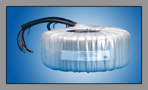
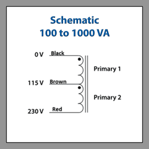
These standard toroidal autotransformers step up or step-down line voltage, to suit your equipment’s input voltage requirement. Autotransformers consist of a single winding with various taps. They provide no isolation since there is no physical separation between the primary and secondary winding.
In circumstances where voltage isolation between the input and output is not needed, autotransformers are ideal. Since the primary and secondary windings of an autotransformer share common turns, you can expect the size and weight reduction of about 30-70%, which results in a significant cost reduction.
| Part Number | Power Rating (VA) | Primary Voltage | Secondary Voltage | Diameter | Height | Weight |
|---|---|---|---|---|---|---|
| XF-A0100A | 100 VA | 115 Vac | 230 Vac | 3.2" | 1.8" | 1.5 lbs |
| XF-A0100B | 100 VA | 230 Vac | 115 Vac | 3.2" | 1.8" | 1.5 lbs |
| XF-A0200A | 200 VA | 115 Vac | 230 Vac | 3.8" | 1.8" | 2.8 lbs |
| XF-A0200B | 200 VA | 230 Vac | 115 Vac | 3.8" | 1.8" | 2.8 lbs |
| XF-A0300A | 300 VA | 115 Vac | 230 Vac | 4.5" | 1.9" | 3.6 lbs |
| XF-A0300B | 300 VA | 230 Vac | 115 Vac | 4.5" | 1.9" | 2.8 lbs |
| XF-A0400A | 400 VA | 115 Vac | 230 Vac | 4.9" | 1.9" | 4.5 lbs |
| XF-A0400B | 400 VA | 230 Vac |
115 Vac |
4.9" | 1.9" | 4.5 lbs |
| XF-A0500A | 500 VA | 115 Vac | 230 Vac | 5.0" | 2.3" | 5.5 lbs |
| XF-A0500B | 500 VA | 230 Vac | 115 Vac | 5.0" | 2.3" | 5.5 lbs |
| XF-A0600A | 600 VA | 115 Vac | 230 Vac | 5.2" | 2.4" | 6 lbs |
| XF-A0600B | 600 VA | 230 Vac | 115 Vac | 5.2" | 2.4" | 6 lbs |
| XF-A0700A | 700 VA | 115 Vac | 230 Vac | 5.4" | 2.6" | 7.5 lbs |
| XF-A0700B | 700 VA | 230 Vac | 115 Vac | 5.4" | 2.6" | 7.5 lbs |
| XF-A0800A | 800 VA | 115 Vac | 230 Vac | 5.6" | 2.5" | 7.5 lbs |
| XF-A0800B | 800 Vac | 230 Vac | 115 Vac | 5.6" | 2.5" | 7.5 lbs |
| XF-A0900A | 900 VA | 115 Vac | 230 Vac | 5.8" | 2.6" | 8.7 lbs |
| XF-A0900B | 900 VA | 230 Vac | 115 Vac | 5.8" | 2.6" | 8.7 lbs |
| XF-A1000A | 1000 VA | 115 Vac | 230 Vac | 5.9" | 2.9" | 9 lbs |
| XF-A1000B | 1000 VA | 230 Vac | 115 Vac | 5.9" | 2.9" | 9 lbs |
Our Standard Toroidal Autotransformers Include The Above Advantages Of Toroidal Transformer And:
- 115 V or 230 V input and a 115 V or 230 V output
- Power ratings ranging from 100 to 1,000 VA
- Standard mounting options (metal disk and gasket)
- 10″ stranded leads
Toroidal Auto Transformer Wiring Diagram 100 VA to 1000 VA
MEDICAL GRADE ISOLATION TRANSFORMERS
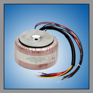
These medical-grade high isolation toroidal transformers are integrated into medical devices used in hospitals, medical research facilities, and biomedical companies.
They assist in bringing these electronic devices into compliance with the UL 60601 medical safety standard for an additional level of safety and protection. Toroidal transformer construction, design, and testing of toroidal medical isolation transformers are strictly monitored under safety regulations, guidelines, and governing laws.
- Minimum air clearance.
- Minimum creepage distance.
- Maximum patient auxiliary current.
- Magnetic field of a toroid lowers stray losses (leakage flux).
- Maximum patient leakage current.
- Maximum enclosure leakage current.
- Limited max. earth leakage current.
- Maximum temperature rise at load and overload.
- The values of test voltage (high potential voltage test between windings).
Standard medical transformers are recognized to UL 60601-1, CSA C22.2 no. 601, and can be quickly and easily configured for your requirement.
Standard Medical Isolation Transformers
| Part Number | Nominal Power VA | Secondary Current at 120V | Secondary Current at 240V | OD x Hieght Inches Weight lbs | Competitor P/N Reference |
|---|---|---|---|---|---|
| MED-0100 | 100 | .83A | .42A | 4.0 x 2.0 2.8 | MT0100DS |
| MED-0200 | 200 | 1.67A | .83A | 4.6 x 2.5 4.8 | MT0230DS |
| MED-0300 | 300 | 2.50A | 1.25A | 5.0 x 3.0 7.2 | N/A |
| MED-0400 | 400 | 3.33A | 1.67A | 5.5 x 3.0 8.8 | MT0400DS |
| MED-0600 | 600 | 5.00A | 2.50A | 6.6 x 2.6 11.4 | MT0600DS |
| MED-0800 | 800 | 6.67A | 3.33A | 6.6 x 3.1 14.2 | N/A |
| MED-1000 | 1000 | 8.33A | 4.17A | 6.6 x 4.25 19.3 | MT1000DS |
| MED-1500 | 1500 | 12.5A | 6.25A | 8.2 x 3.9 25.6 | MT1500DS |
| MED-2000 | 2000 | 16.67A | 8.33A | 9.0 x 4.0 31.8 | MT2000DS |
| MED-2500 | 2500 | 20.83A | 10.42A | 9.0 x 4.3 40 | MT2500DS |
| MED-3000 | 3000 | 25.0A | 12.5A | 10.2 x 4.3 47 | MT3000DS |
| MED-4000 | 4000 | 33.33A | 16.67A | 11.3 x 4.0 56 | N/A |
| MED-5000 | 5000 | 41.67A | 20.83A | 12.36 x 4.5 74 | MT5000DS |
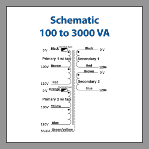
Toroidal Isolation Transformer Wiring Diagram – Medical Grade Isolation Transformers 100 to 3000 VA
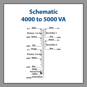
Toroidal Isolation Transformer Wiring Diagram – Medical Grade Isolation Transformers 4000 to 5000 VA
Custom Toroidal Medical Grade Isolation Transformer Designs
We can also provide custom medical isolations transformer designs to fit your specific needs. The popular configurations have a combination of the following including the above advantages of toroidal transformers:
- Custom primary and secondary voltage.
- Variety of connection and harnessing options.
- Magnetic field of a toroid lowers stray losses (leakage flux).
- Custom mounting and enclosures to meet customer requirements.
- Low height/easily configured into minimal space.
- Custom medical transformer designs can be added to our UL medical file for a nominal charge.
LOW PROFILE MINIATURE TOROIDAL ISOLATION TRANSFORMERS
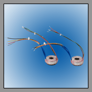
Our low-profile miniature toroid isolation transformers are rated for 50/60Hz operation and have capacities up to 50 VA. Toroidal power transformers are mainly used in 115/230 V (50/60Hz) applications. They are easily mounted by using a single M4 bolt inserted in a through-hole provided in the center of the potting. This provides a secure and reliable means of mounting.
These toroidal power transformers are built to UL class A insulation system and are UL recognized to UL 5085-1 and UL 5085. They’re also C-UL recognized to CSA C22.2 no. 66 and toroidal transformer construction meets the requirements of UL 1950 VDE 0805 IEC 950 and EN60950.
| Power VA | Part Number | Competitor P/N Reference | Full Load Voltage (U0) | Current mA | No Load Voltage (U0) | No-Load Current | Reg. % | Δt ˚C | Eff % | Dim. lxWxH mm |
|---|---|---|---|---|---|---|---|---|---|---|
| 1.6 | XF-10200 XF-10201 XF-10202 XF-10203 XF-10204 XF-10205 | 62000 62001 62002 62003 62004 62005 | 2x7 2x9 2x12 2x15 2x18 2x22 | 114 89 67 53 44 36 | 2x8.94 2x11.63 2x15.43 2x19.30 2x23.41 2x28.19 | 1.0 (mA) | 29 | 10 | 77 | 37.5x7.0x17.0 71 (grams) |
| 3.2 | XF-10206 XF-10207 XF-10208 XF-10209 XF-10210 XF-10211 | 62010 62011 62012 62013 62014 62015 | 2x7 2x9 2x12 2x15 2x18 2x22 | 229 178 133 107 89 73 | 2x10.2 2x13.0 2x17.3 2x21.4 2x25.7 2x31.3 | 1.5 (mA) | 41 | 20 | 70 | 42.0x7.0x17.5 89 (grams) |
| 5.0 | XF-10212 XF-10213 XF-10214 XF-10215 XF-10216 XF-10217 | 62020 62021 62022 62023 62024 62025 | 2x7 2x9 2x12 2x15 2x18 2x22 | 357 278 208 167 139 114 | 2x9.7 2x12.4 2x17.0 2x21.3 2x25.5 2x30.5 | 2.0 (mA) | 45 | 29 | 70 | 47.0x6.0x18.0 115 (grams) |
| 7.0 | XF-10218 XF-10219 XF-10220 XF-10221 XF-10222 XF-10223 | 62030 62031 62032 62033 62034 62035 | 2x7 2x9 2x12 2x15 2x18 2x22 | 500 389 292 233 194 159 | 2x9.5 2x12.2 2x16.2 2x20.3 2x24.3 2x29.7 | 3.0 (mA) | 34 | 25 | 74 | 47.0x6.0x21.5 145 (grams) |
| 10.0 | XF-10224 XF-10225 XF-10226 XF-10227 XF-10228 XF-10229 | 62040 62041 62042 62043 62044 62045 | 2x7 2x9 2x12 2x15 2x18 2x22 | 714 556 417 333 278 227 | 2x8.3 12x10.8 2x14.4 2x18.0 2x21.7 2x26.3 | 3.0 (mA) | 20 | 24 | 82 | 53.5x6.8x23.5 216 (grams) |
| 15.0 | XF-10230 XF-10231 XF-10232 XF-10233 XF-10234 XF-10235 | 62050 62051 62052 62053 62054 62055 | 2x7 2x9 2x12 2x15 2x18 2x22 | 1071 833 625 500 417 341 | 2x8.9 2x11.1 2x14.8 2x18.5 2x22.2 2x27.2 | 4.0 (mA) | 23 | 27 | 81 | 57.5x7.0x24.0262 (grams) |
| 25.0 | XF-10236 XF-10237 XF-10238 XF-10239 XF-10240 XF-10241 | 62060 62061 62062 62063 62064 62065 | 2x7 2x9 2x12 2x15 2x18 2x22 | 1785 1377 1041 832 694 568 | 2x8.3 2x10.7 2x14.2 2x17.8 2x21.4 2x26.2 | 5.0 (mA) | 19 | 28 | 84 | 58.0x13.8x34.5 388 (grams) |
| 35.0 | XF-10242 XF-10243 XF-10244 XF-10245 XF-10246 XF-10247 | 62070 62071 62072 62073 62074 62075 | 2x7 2x9 2x12 2x15 2x18 2x22 | 2500 1944 1458 1166 972 795 | 2x8.4 2x10.6 2x14.0 2x17.6 2x20.9 2x25.7 | 7.0 (mA) | 17.7 | 31 | 85 | 72.0x17.0x33.5 453 (grams) |
| 50.0 | XF-10248 XF-10249 XF-10250toroidal-transformers XF-10251 XF-10252 XF-10253 | 62080 62081 62082 62083 62084 62085 | 2x7 2x9 2x12 2x15 2x18 2x22 | 3571 2777 2083 1666 1388 1136 | 2x8.1 2x10.4 2x13.8 2x17.3 2x20.7 2x25.4 | 8.0 (mA) | 15.5 | 30 | 86 | 78.0x22.5x35.0 670 (grams) |
Assembly Drawing Low Profile Miniature Isolation Transformers
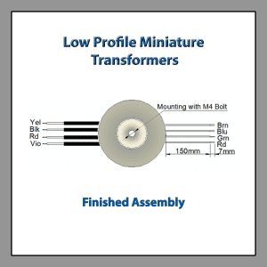
Toroidal Isolation Transformer Wiring Diagram Low Profile Miniature Isolation Transformers
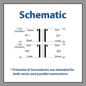
Low Profile Toroid Isolation Transformers offer:
- Greater efficiency.
- The magnetic field of a toroid lowers stray losses (leakage flux).
- Lower audible vibration.
- Easier mounting.
LOW PROFILE PC MOUNT TOROIDAL ISOLATION TRANSFORMERS
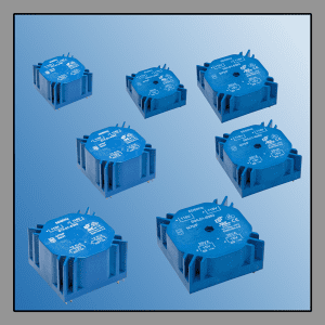
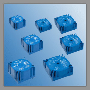
Our low-profile PCB Mount toroidal power transformers come fully encapsulated in a plastic case. These are designed for through-hole PCB mounting and are provided with a built-in central screw holder that will accommodate M4/M5 machine screws or self-tapping screws. This permits you to secure the toroidal Isolation transformer to the PC board before soldering.
There is also room inside the case allowing for other components to be included with the transformer to form a homogeneous unit. Typical components that can be added include PTC thermistors, fuses, re-settable thermal switches, rectifiers, and voltage regulators.
All low-profile PC mount toroidal isolation transformer models are configured for 2x115 V Input voltages at 50/60Hz. They pass high voltage testing at 0.5 KVAC between primary to primary, secondary to secondary, and 4 kV primary to secondary. They are specified at an ambient temperature of 70°F and can withstand elevated ambient temperatures of up to 70˚C.
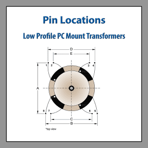
Standard Low Profile PC Mount Toroidal Isolation Transformer Dimensions
| VA RATING | L | W | H | A | B | C | D | toroidal-transformersE |
|---|---|---|---|---|---|---|---|---|
| 1.6 | 39.6 | 39.6 | 18.5 | 35.56 | 35.56 | 25.4 | 30.48 | 20.32 |
| 3.2 | 44.7 | 44.7 | 19.5 | 40.64 | 40.64 | 30.48 | 35.56 | 25.4 |
| 5 | 49.7 | 49.7 | 19.5 | 45.72 | 45.72 | 35.56 | 40.64 | 30.48 |
| 7 | 49.7 | 49.7 | 23.1 | 45.72 | 45.72 | 35.56 | 40.64 | 30.48 |
| 10 | 55 | 55 | 26 | 50.8 | 50.8 | 40.64 | 45.72 | 35.56 |
| 15 | 60 | 60 | 26.3 | 55.88 | 55.88 | 45.72 | 50.8 | 40.64 |
| 25 | 60 | 60 | 37.5 | 55.88 | 55.88 | 45.72 | 50.8 | 40.64 |
| 35 | 72 | 72 | 37.5 | 66.04 | 66.04 | 55.88 | 60.96 | 50.8 |
| 50 | 82.4 | 82.4 | 37.5 | 76.2 | 76.2 | 66.04 | 71.12 | 60.96 |
Pin Locations Drawing Low Profile PC Mount Transformers
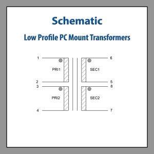
Toroidal Isolation Transformer Wiring Diagram Low Profile PC Mount Transformers
Standard Low Profile PC Mount Toroidal Isolation Transformers
| 1.6 VA | Part Number | Competitor P/N Reference | Secondary | Resistance 20°C | Design Details | ||
|---|---|---|---|---|---|---|---|
| L01-6300 | 70000 | 2 x | 7V 114 mA | 2 x 9V | 2 x 8.80Ω | Weight total = 80 g Weight Cu = 20 g Efficiency = 77% External Fuse 32mA (stb) at 230V Fixing = M4 threaded screw | |
| L01-6301 | 70001 | 2 x | 9V 89 mA | 2 x 11.6V | 2 x 15.8Ω | ||
| L01-6302 | 70002 | 2 x | 12V 67 mA | 2 x 15.4V | 2 x 26.9Ω | ||
| L01-6303 | 70003 | 2 x | 15V 53 mA | 2 x 19.3V | 2 x 43.4Ω | ||
| L01-6304 | 70004 | 2 x | 18V 44 mA | 2 x 23.4V | 2 x 65.9Ω | ||
| *L01-6305 | 70005 | 2 x | 22V 36 mA | 2 x 28.2V | 2 x 88.1Ω | ||
| 3.2 VA | Part Number | Competitor P/N Reference | Secondary | Resistance 20°C | Design Details | ||
| L01-6310 | 70010 | 2 x | 7V 229 mA | 2 x 10.2V | 2 x 7.0Ω | Weight total = 110 g Weight Cu = 26 g Efficiency = 70% External Fuse 32mA (stb) at 230V Fixing = M4 threaded screw | |
| L01-6311 | 70011 | 2 x | 9V 178 mA | 2 x 13.0V | 2 x 11.3Ω | ||
| L01-6312 | 70012 | 2 x | 12V 133 mA | 2 x 17.3V | 2 x 20.7Ω | ||
| L01-6313 | 70013 | 2 x | 15V 107 mA | 2 x 21.4V | 2 x 28.9Ω | ||
| *L01-6314 | 70014 | 2 x | 18V 89 mA | 2 x 25.7V | 2 x 45.4Ω | ||
| *L01-6315 | 70015 | 2 x | 22V 73 mA | 2 x 31.3V | 2 x 62.2Ω | ||
| 5 VA | Part Number | Competitor P/N Reference | Secondary | Resistance 20°C | Design Details | ||
| L01-6320 | 70020 | 2 x | 7V 357 mA | 2 x 9.7V | 2 x 4.0Ω | Weight total = 144 g Weight Cu = 33 g Efficiency = 68% External Fuse 50mA (stb) at 230V Fixing = M4 threaded screw | |
| L01-6321 | 70021 | 2 x | 9V 278 mA | 2 x 12.4V | 2 x 6.5Ω | ||
| L01-6322 | 70022 | 2 x | 12V 208 mA | 2 x 17.0V | 2 x 12.3Ω | ||
| L01-6323 | 70023 | 2 x | 15V 167 mA | 2 x 21.3V | 2 x 19.0Ω | ||
| *L01-6324 | 70024 | 2 x | 18V 139 mA | 2 x 25.5V | 2 x 28.8Ω | ||
| *L01-6325 | 70025 | 2 x | 22V 114 mA | 2 x 30.5V | 2 x 39.1Ω | ||
| 7 VA | Part Number | Competitor P/N Reference | Secondary | Resistance 20°C | Design Details | ||
| L01-6330 | 70030 | 2 x | 7V 500 mA | 2 x 9.5V | 2 x 2.5Ω | Weight total = 174 g Weight Cu = 36 g Efficiency = 74% External Fuse 63mA (stb) at 230V Fixing = M4 threaded screw | |
| L01-6331 | 70031 | 2 x | 9V 389 mA | 2 x 12.2V | 2 x 4.1Ω | ||
| L01-6332 | 70032 | 2 x | 12V 292 mA | 2 x 16.2V | 2 x 7.7Ω | ||
| L01-6333 | 70033 | 2 x | 15V 233 mA | 2 x 20.3V | 2 x 12.0Ω | ||
| L01-6334 | 70034 | 2 x | 18V 194 mA | 2 x 24.3V | 2 x 17.9Ω | ||
| *L01-6335 | 70035 | 2 x | 22V 159 mA | 2 x 29.7V | 2 x 24.4Ω | ||
| 10 VA | Part Number | Competitor P/N Reference | Secondary | Resistance 20°C | Design Details | ||
| L01-6340 | 70040 | 2 x | 7V 714 mA | 2 x 8.3V | 2 x 1.0Ω | Weight total = 252 g Weight Cu = 45 g Efficiency = 82% External Fuse 80mA (stb) at 230V Fixing = M4 threaded screw | |
| L01-6341 | 70041 | 2 x | 9V 556 mA | 2 x 10.8V | 2 x 1.7Ω | ||
| L01-6342 | 70042 | 2 x | 12V 417 mA | 2 x 14.4V | 2 x 3.2Ω | ||
| L01-6343 | 70043 | 2 x | 15V 333 mA | 2 x 18.0V | 2 x 5.0Ω | ||
| L01-6344 | 70044 | 2 x | 18V 278 mA | 2 x 21.7V | 2 x 7.5Ω | ||
| *L01-6345 | 70045 | 2 x | 22V 227 mA | 2 x 26.3V | 2 x 10.3Ω | ||
| 15 VA | Part Number | Competitor P/N Reference | Secondary | Resistance 20°C | Design Details | ||
| L01-6350 | 70050 | 2 x | 7V 1071 mA | 2 x 8.9V | 2 x 0.85Ω | Weight total = 304 g Weight Cu = 57 g Efficiency = 80% External Fuse 100mA (stb) at 230V Fixing = M4 threaded screw | |
| L01-6351 | 70051 | 2 x | 9V 833 mA | 2 x 11.1V | 2 x 1.3Ω | ||
| L01-6352 | 70052 | 2 x | 12V 625 mA | 2 x 14.8V | 2 x 2.3Ω | ||
| L01-6353 | 70053 | 2 x | 15V 500 mA | 2 x 18.5V | 2 x 3.1Ω | ||
| L01-6354 | 70054 | 2 x | 18V 417 mA | 2 x 22.2V | 2 x 5.3Ω | ||
| *L01-6355 | 70055 | 2 x | 22V 341 mA | 2 x 27.2V | 2 x 7.4Ω | ||
| 25 VA | Part Number | Competitor P/N Reference | Secondary | Resistance 20°C | Design Details | ||
| L01-6360 | 70060 | 2 x | 7V 1785 mA | 2 x 8.3V | 2 x 0.4Ω | Weight total = 435 g Weight Cu = 85 g Efficiency = 83% External Fuse 100mA (stb) at 230V Fixing = M4 threaded screw | |
| L01-6361 | 70061 | 2 x | 9V 1377 mA | 2 x 10.7V | 2 x 0.7Ω | ||
| L01-6362 | 70062 | 2 x | 12V 1041 mA | 2 x 14.3V | 2 x 1.3Ω | ||
| L01-6363 | 70063 | 2 x | 15V 832 mA | 2 x 17.8V | 2 x 2.0Ω | ||
| L01-6364 | 70064 | 2 x | 18V 694 mA | 2 x 21.4V | 2 x 2.7Ω | ||
| *L01-6365 | 70065 | 2 x | 22V 568 mA | 2 x 26.2V | 2 x 4.1Ω | ||
| 35 VA | Part Number | Competitor P/N Reference | Secondary | Resistance 20°C | Design Details | ||
| L01-6370 | 70070 | 2 x | 7V 2500 mA | 2 x 8.2V | 2 x 0.19Ω | Weight total = 590 g Weight Cu = 187 g Efficiency = 82% External Fuse 200mA (stb) at 230V Fixing = M5 threaded screw | |
| L01-6371 | 70071 | 2 x | 9V 1944 mA | 2 x 10.6V | 2 x 0.32Ω | ||
| L01-6372 | 70072 | 2 x | 12V 1458 mA | 2 x 14.0V | 2 x 0.53Ω | ||
| L01-6373 | 70073 | 2 x | 15V 1167 mA | 2 x 17.6V | 2 x 0.84Ω | ||
| L01-6374 | 70074 | 2 x | 18V 972 mA | 2 x 20.9V | 2 x 1.10Ω | ||
| *L01-6375 | 70075 | 2 x | 22V 795 mA | 2 x 25.7V | 2 x 1.34Ω | ||
| 50 VA | Part Number | Competitor P/N Reference | Secondary | Resistance 20°C | Design Details | ||
| L01-6380 | 70080 | 2 x | 7V 3571 mA | 2 x 8.1V | 2 x 0.13Ω | Weight total = 800 g Weight Cu = 209 g Efficiency = 85% External Fuse 315mA (stb) at 230V Fixing = M5 threaded screw | |
| L01-6381 | 70081 | 2 x | 9V 2777 mA | 2 x 10.4V | 2 x 0.20Ω | ||
| L01-6382 | 70082 | 2 x | 12V 2083 mA | 2 x 13.9V | 2 x 0.34Ω | ||
| L01-6383 | 70083 | 2 x | 15V 1666 mA | 2 x 17.3V | 2 x 0.54Ω | ||
| L01-6384 | 70084 | 2 x | 18V 1389 mA | 2 x 20.8V | 2 x 0.82Ω | ||
| *L01-6385 | 70085 | 2 x | 22V 1136 mA | 2 x 25.4V | 2 x 1.25Ω | ||
Advantages of Low Profile PC Mount Toroidal Isolation Transformers:
- Low profile
- The low stray magnetic field of a toroid magnetic reduced external field radiation.
- Acoustic noise virtually eliminated
- Compact size
- High efficiency
- Low leakage losses
- 4 kV isolation between primary and secondary windings
- Manufactured in an ISO 9001 approved facility
- Comply to UL 5085 and VDE 61558 (except for all 2 x 22 V models)
- Bear the CE mark
- Designed and built to meet Class F (155˚C) insulation system requirements
Additional Features of Low Profile PC Mount Toroidal Isolation Transformers Include The Above Advantages Of Toroidal Transformer and:
- Primary intended to be used in 115 V or 230 V @ 50/60Hz.
- UL recognition for class A insulation.
- UL recognized to UL 5085-1 and UL 5085-2.
- C-UL recognized to CSA C22.2 no. 66.
- Toroidal transformer construction meets UL 1950, VDE 0805, IEC 950.
- Hipot testing between Primary to Secondary 4000 V (VDE0550).
- Maximum ambient temperature of +60°C.
- Magnetic field of a toroid lowers stray losses (leakage flux).
- Center hole potted for an M4 bolt.
TOROIDAL POWER INDUCTORS 50/60HZ
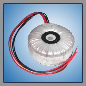
These standard power chokes come in ratings from 0.2Ws to 25Ws. Toroidal power chokes are most commonly used in line frequency (50/60Hz) AC circuits as part of a DC filter. By using a toroidal power choke, you can reduce the physical size of the overall filter.
This is through the size reduction yielded by the toroidal power inductor design and also the required filter capacitors in your LC circuit. The magnetic field of a toroid power inductor also contains any stray magnetic field, further enhancing your filter design.
Standard Toroidal Power Inductors 50/60Hz
| Part Number | Competitor P/N Reference | Current I DC (A) | Current RMS | L (mH) | Power (WS) | Losses Core-Copper | OD x HT (Inches) | OD x HT (mm) | WT (Ibs.) | WT (kg) |
|---|---|---|---|---|---|---|---|---|---|---|
| IND-0540 IND-0560 | L0540 L0560 | 5 5 | 3.5 3.5 | 40 60 | 0.5 0.75 | 1.5 - 12.8 3 - 13.8 | 3.8x1.9 4.6x2.0 | 97x48 117x51 | 2.5 4 | 1.1 1.8 |
| IND-1020 IND-1040 IND-1060 | L1020 L1040 L1060 | 10 10 10 | 7 7 7 | 20 40 60 | 1 2 3 | 4 - 16.7 5 - 23.4 7 - 28.6 | 5.5x2.0 5.5x2.4 5.9x2.8 | 140x51 140x61 150x71 | 6 8 11.5 | 2.7 3.6 5.2 |
| IND-1510 IND-1515 IND-1520 IND-1540 | L1510 L1515 L1520 L1540 | 15 15 15 15 | 10.6 10.6 10.6 10.6 | 10 15 20 40 | 1.13 1.69 2.25 4.5 | 4 - 18.7 5 - 22.7 5 - 26.3 8 - 37.8 | 5.5x2.0 5.5x2.4 5.9x2.8 6.5x2.8 | 140x51 140x61 140x61 165x71 | 6 7.5 8 15 | 2.7 3.4 3.6 6.8 |
| IND-2010 IND-2015 IND-2020 IND-2040 | L2010 L2015 L2020 L2040 | 20 20 20 20 | 14.1 14.1 14.1 14.1 | 10 15 20 40 | 2 3 4 8 | 5 - 23.2 7 - 28.4 8 - 32.8 12 - 42.8 | 5.5x2.4 5.9x2.8 6.5x2.8 8.0x3.5 | 140x61 150x71 165x71 203x89 | 8 11.5 14 27 | 3.6 5.2 6.4 12.3 |
| IND-3005 IND-3010 IND-3015 IND-3020 | L3005 L3010 L3015 L3020 | 30 30 30 30 | 21.2 21.2 21.2 21.2 | 5 10 15 20 | 2.25 4.5 6.75 9 | 5 - 26.1 8 - 37.8 11 - 45.9 13 - 43.2 | 5.5x2.4 6.5x2.8 8.0x3.0 8.0x3.5 | 140x61 165x71 203x76 203x89 | 8.5 15 22 28 | 3.9 6.8 10.0 12.7 |
| IND-4005 IND-4010 IND-4015 | L4005 L4010 L4015 | 40 40 40 | 28.3 28.3 28.3 | 5 10 15 | 4 8 12 | 8 - 32 13 - 43.2 20 - 56 | 6.5x2.8 8.0x3.5 10x3.4 | 165x71 203x89 254x86 | 14 27 39 | 6.4 12.3 17.7 |
| IND-5005 IND-5010 | L5005 L5010 | 50 50 | 35.3 35.3 | 5 10 | 6.25 12.5 | 11 - 35 20 - 57.5 | 8.0x3.0 10.0x3.4 | 203x76 254x86 | 23 39 | 10.4 17.7 |
| IND-6005 | L6005 | 60 | 42.4 | 5 | 9 | 12 - 43.2 | 8.0x3.5 | 203x89 | 29 | 13.2 |
Toroid Toroidal Power Inductors 50/60Hz offer:
- Greater efficiency
- Lower audible vibration
- Easier mounting
- Lower stray losses (leakage flux)