About Neutral Grounding Resistors
A Neutral Ground Resistor, sometimes called Neutral Earthing Resistor (NERs) is commonly used as part of a Low Resistance Grounding System in industrial distribution systems. The NGR will limit fault currents that flow through the neutral star point of a transformer or generator, to a safe reasonable predetermined value during a fault event.
The Neutral Ground Resistor is a high-power resistor normally using grid resistors in their construction but sometimes uses wire wound resistor elements. Our NGRs are made using a Heavy-Duty Grid Resistor from low-temperature coefficient Fe-Cr-Al Stainless Steel alloy, that is compliant with the applicable new standard IEEE-C57.32, 2015 “Requirements, Terminology, and Test Procedure for Neutral Grounding Devices”. These high power resistors are designed to permit thermal expansion under rated duty with spot-welded stainless-steel jumpers between grid resistor banks (for lower power units wire wound resistor). Ceramic spacers and ANSI Standoffs electrically isolate the resistive elements.
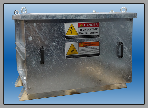
A Neutral Earthing Resistor (NER) or Neutral Grounding Resistor can be supplied with outdoor or indoor enclosures with appropriate ingress protection levels. In the case of an outdoor enclosure, the material can be mild steel finished in a powder coat or Hot Dip Galvanized. Hot Dip Galvanized enclosures are built according to ISO 1461:1999. This ensures a high degree of protection.


against corrosion, fabricated from min 14 gauge mild steel (12 gauge for feet &side supports). Our metal parts are galvanized after all sheet metal processing operations (drilling, cutting, etc.) are completed and the unit is pre-assembled for quality check and disassembled after approval. This two-stage approval before galvanizing is a crucial requirement to prevent any uncoated part, which may adversely affect the corrosion performance during service. Other enclosure options are unpainted 14-gauge AISI 304 (EN 1.4301) stainless steel to provide the best outdoor protection available.
Because of the heat generated by the Neutral Grounding Resistor power resistor resistive elements, slots, and louvers are included in the enclosure to provide adequate ventilation for rapid cooling. Eyebolts for lifting and easy handling are provided along with Optional Window Type Current Transformers and Terminal Box for CT secondary (Optional). All stainless steel hardware is standard for added durability.
This safe level of fault current allows for selective and fast fault detection by means of simple over-current relays, to avoid network shutdown and equipment damage. In addition, this flow of fault current can activate protection devices to locate and clear the fault.
NGRs (neutral grounding resistors) dissipate and absorb an enormous amount of energy for the duration of the fault event without exceeding temperature limitations as defined in IEEE Standard 32-1972, typically 760C. Units are tested to all requirements prescribed by NEMA, ANSI, and IEEE Standard C57.321972 2015.

Parts of an NGR
Typically, our NGRs are outdoor rated units enclosed in NEMA/3R/IP23 enclosure either stainless steel or hot dip Galvanized. The enclosure includes lifting eye bolts, and a porcelain bushing provides the medium voltage connection, earth terminal, and heavy-duty mounting feet. Internally the high power resistor elements consist of FE-Cr-Al Stainless steel grid resistors elements which are Isolated from the enclosure by porcelain side supports and stand-off insulators. Provisions are made for an optional Neutral Current Transformer where the secondary leads can be wired to a terminal block for field interconnection to a ground fault relay. Are you building or integrating a Neutral Grounding Resistor into your equipment? We offer fully assembled open stacks of stainless-steel grid resistor elements with porcelain side supports and stand-off insulators for easy installation in your enclosure. This solution is perfect for resistive load banks for large medium voltage generator enclosure manufacturers, load testing, or creating generator load banks.
NGRs provide the following benefits:
- Reduces stress and the amount of damage to your power system equipment.
- Rapid isolation and clearing of the original fault.
- Electrical distribution network security is improved.
- For generators, it limits the amount available of Line to Neutral fault current to below the design limits set by the NEMA MG1 generators design standard.
- Decrease in unplanned shutdowns.
- Prolong the life of transformers or other connected distribution equipment.
- Are suitable for generator testing and generator load banks.
Also, consider our Grid resistors and wire wound resistor assemblies for:
- Generator load testing.
- Hybrid capacitive and resistor load banks.
- Medium voltage power resistors
- Medium voltage generator testing
- Grid resistors assemblies
- High power resistors load banks.
What is the purpose of a Neutral Grounding Resistor?
Typically, NGRs are used in conjunction with generators or motors. With both of these devices, ground fault currents can be extremely high and if not controlled can result in damage to transformers, generators, motors, wiring, and associated equipment. Moreover, a neutral grounding resistor for generators will avoid damaging the stator core. Stator cores consist of laminations made from silica-steel, cold-rolled or grain-oriented steel. If damage were to occur to the Stator core it could result in the complete replacement of the motor/generator or a costly off-site repair. If just the winding were to be damaged, this also is costly but not catastrophic and can be completed by a local rewinding house. In each of these cases, a Neutral Earthing Resistor is used to prevent damage from occurring in the first place. It is also common to use grid resistor based NGRs as a resistor load bank when doing medium voltage generator load testing. Generator testing normally requires high power resistors to serve as generator load banks during load testing generators.
To limit the damage to the core, generator, and motor manufacturers allow for a limited ground fault current, which is usually provided by the manufacturer in terms of Core Damage Curves. By inserting a Neutral Ground Resistor (NGR) between the system neutral and ground, it lowers the prospective ground-fault current to a predetermined value; note below our standard 10s values of 100 to 1000A. By controlling the magnitude of the ground fault currents, it will reduce the stress and amount of damage to your power system equipment. Connecting an NGR to the neutral of a generator will limit the amount of the generator available Line to Neutral fault current to below the design limits set by the NEMA MG1 generators design standard. Another advantage of a Neutral Earthing Resistor system is that ground fault current can flow, permitting it to be detected and measured. Simple over-current relays allow a selective and fast fault detection, that can be used on feeders to provide careful coordination and the ability to quickly pinpoint and isolate the fault. Depending on the application, the resistor can be designed for either a high or low current value or continuous or a predetermined duration. The grid resistors designed for maximum current allow relays and protection settings to be effortlessly determined with the goal of avoiding damage to equipment, providing a safe operating environment and continuity of supply.There are several methods of Neutral Grounding
We offer High and Low resistance grounding resistors
Medium and high voltage electrical networks use Low Resistance Grounding because of the high capital equipment used in these applications and the high cost of network interruption. NGRs are sized to permit 100A to 2500A of fault current, with typical time durations of 10s. This current permits protective devices to operate but does not allow major equipment damage. We provide NGRs with standard Line-to-Line voltages of 2400, 4160, 4800, 6900, 7200, 8320, 12000, 12470, 13200 and 13800. Custom designs up to 111kV are possible.Continuous process industries will typically use High Resistance Grounding using wire wound resistor elements because these commercial systems require continuous operation, even after a fault occurs. Our NGRs will reduce the current to a low value, 10 Amps or less. This occurs, so circuit breakers are not tripped and allow for Protection Systems to activate during this event, quickly locating and clearing the fault or providing for an orderly shutdown of the system so no damage occurs.

Standard Low Resistance - Neutral Ground Resistor
Standard NGRs can be operated at a 120°F maximum ambient temperature, 0°F minimum ambient temperature, and an altitude of 1000 m. For altitudes above 1000 m, unique designs are available to accommodate the dielectric strength of insulation parts corrected according to the given service altitude for up to and including 6000 m as per IEEE C37.20.2 NGRs are designed and factory tested to IEEE Standard C57.32-2015 and are designed to meet all applicable specifications of ANSI, NEC, NFPA, NEMA, and OSHA.. These conform to Seismic Zone 2 requirements of the Uniform Building Code unless otherwise specified. These are also suitable for medium voltage generator testing and resistor load banks.Standard Enclosed NGRs Electrical Ratings
5kV Class
| System Voltage (L-L) | L-N Voltage | Current Ratings* |
|---|---|---|
| 2400 | 1385 | 100/200/300/400 Amps |
| 4160 | 2400 | 100/200/300/400 Amps |
| 4800 | 2770 | 100/200/300/400 Amps |
| 6900 | 4000 | 100/200/300/400 Amps |
| 7200 | 4160 | 100/200/300/400/800/1000 Amps |
| 8320 | 4800 | 100/200/300/400 Amps |
15kV Class
| System Voltage (L-L) | L-N Voltage | Current Ratings* |
|---|---|---|
| 12000 | 6930 | 100/200/300/400 Amps |
| 12470 | 7200 | 100/200/300/400/500/600 Amps |
| 13200 | 7620 | 100/200/300/400/500/600 Amps |
| 13800 | 8000 | 100/200/300/400/500/600 Amps |
Standard Mechanical Ratings**
| System Voltage (L-L) | Width inches | Depth inches | Height inches | Weight lbs. |
|---|---|---|---|---|
| 2400 | 40 | 38 | 30 | 330 |
| 4160 | 40 | 38 | 30 | 330 |
| 4800 | 40 | 38 | 30 | 330 |
| 6900 | 40 | 38 | 30 | 330 |
| 7200 | 40 | 38 | 30 | 330 |
| 8320 | 40 | 38 | 30 | 330 |
| 12000 | 52 | 52 | 57 | 770 |
| 12470 | 52 | 52 | 57 | 770 |
| 13200 | 52 | 52 | 57 | 770 |
| 13800 | 52 | 52 | 57 | 770 |
Standard NGR design details
Our NGRs are enclosed in outdoor NEMA/3R/IP23 enclosure, allowing for bottom entry and safety exit. They are fully assembled with options for a Neutral Current Transformer installed in an enclosure, with secondary leads wired to the terminal blocks for field interconnection to a ground fault relay. These are also suitable for medium voltage generator testing and resistor load banks.
How to Size a Neutral Grounding Resistor?
Consider the following parameters
- Rated Line-to-Line voltage or Line-to-Neutral voltage.
- The time duration of the NGR will carry the maximum current.
- Short time rating: typically, 10 seconds or 60 seconds.
- Continuous rating: normally 5% to 10 % of total load current.
- Maximum current when the resistor is cold.
- Insulation is specified based on line voltage.
- The maximum short-time temperature rise for the resistive element is 760°C, in accordance with IEEE Standard 32-1972 (Requirements, Terminology and Test Procedure for Neutral Grounding Devices).
- Ingress protection IP rating for outdoor or indoor enclosures. Standard enclosures are manufactured having IP10, IP13, or IP23.
- Enclosure material can be mild steel, finished in a powder coat or hot-dip galvanized, or stainless steel.
- Auxiliary items: Voltage transformers, off-load isolators, current transformers, or other options.